¶ Preparation
¶ Install Board Files
After checking the board status, you can start developing new projects. To facilitate users to quickly develop, we provide a board file for this board. After downloading, copy the folder "iw-rfsoc-2t2r-47dr" into Vivado/<version>/data/boards/board_files/. If there is no board_files directory, create one yourself. Open Vivado and you can select the "IW-RFSOC-2T2R" board. <version> is the Vivado version number you are using.
In the following content, we will use this as a basis to develop the project step by step.
¶ Create Memory Test Project
¶ Create a New Blank Project
In the "Default Part" stage when creating a project, select the "Boards" tab, select the "Interwiser RFSoC 2T2R Development Kit" board in the board list, and then click "Next".
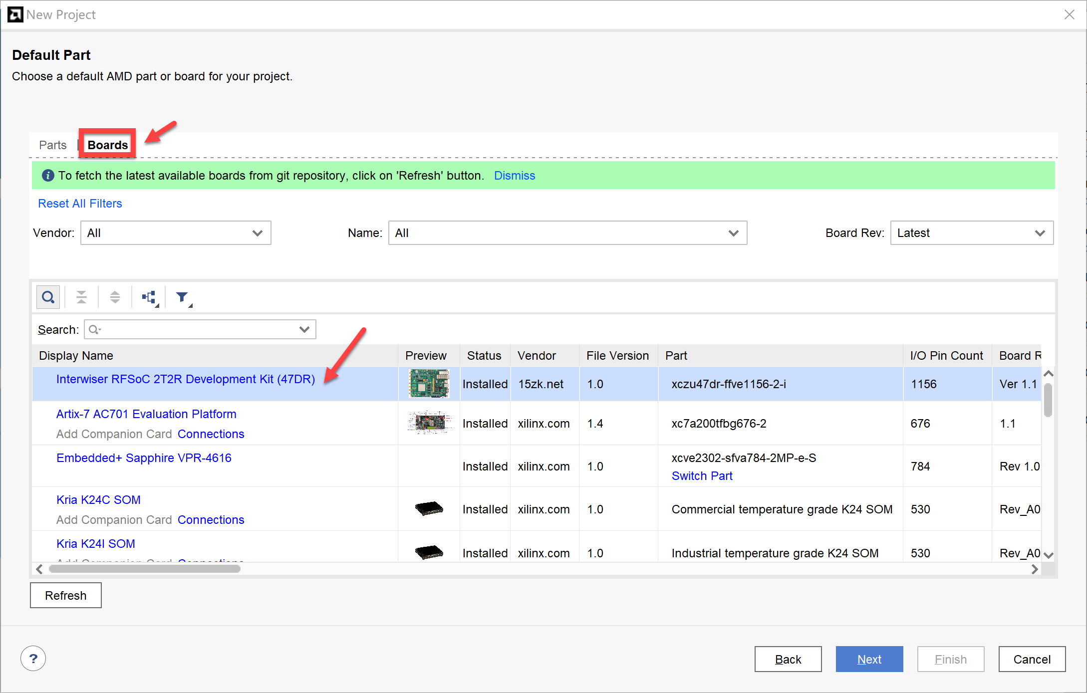
If you don't find the board file shown in the figure at this stage, please check if the file is correctly installed. Note! You need to copy the entire "iw-rfsoc-2t2r-47dr" folder into the "board_files" folder, not just its subfolders.
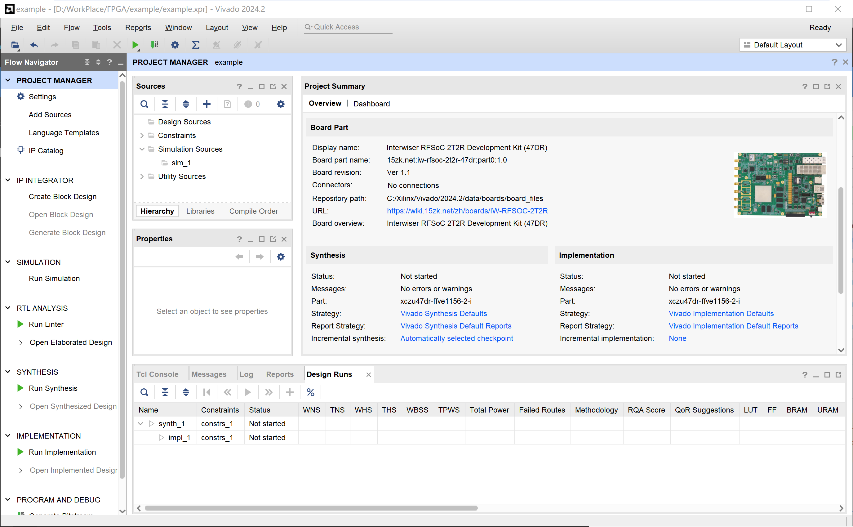
If the creation is successful, you should see the following interface.
¶ Add and Configure Zynq Module
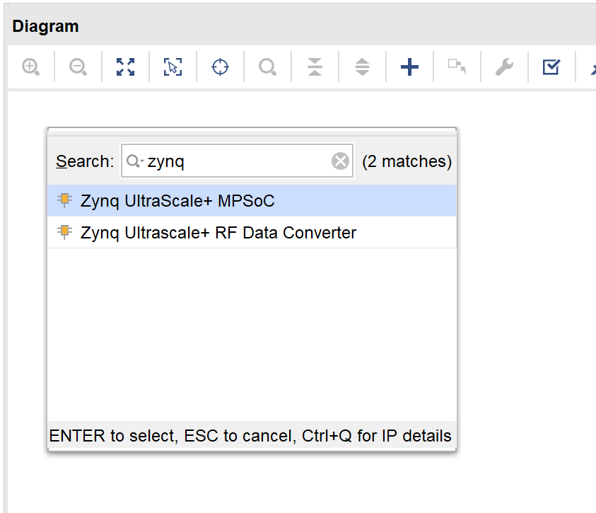
Create a new "Block Design" and add a "Zynq UltraScale+ MPSoC" instance.
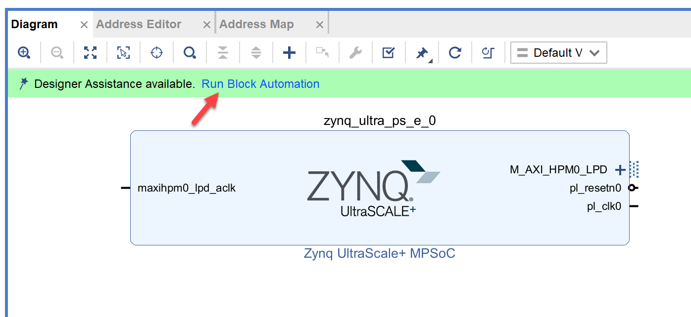
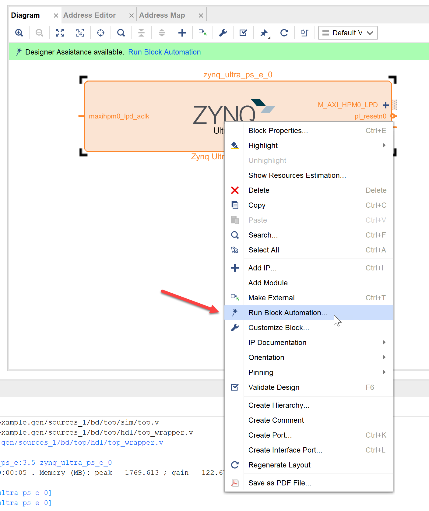
Click the automatically popped up "Run Block Automation" or right-click the "ZYNQ" instance and select "Run Block Automation".
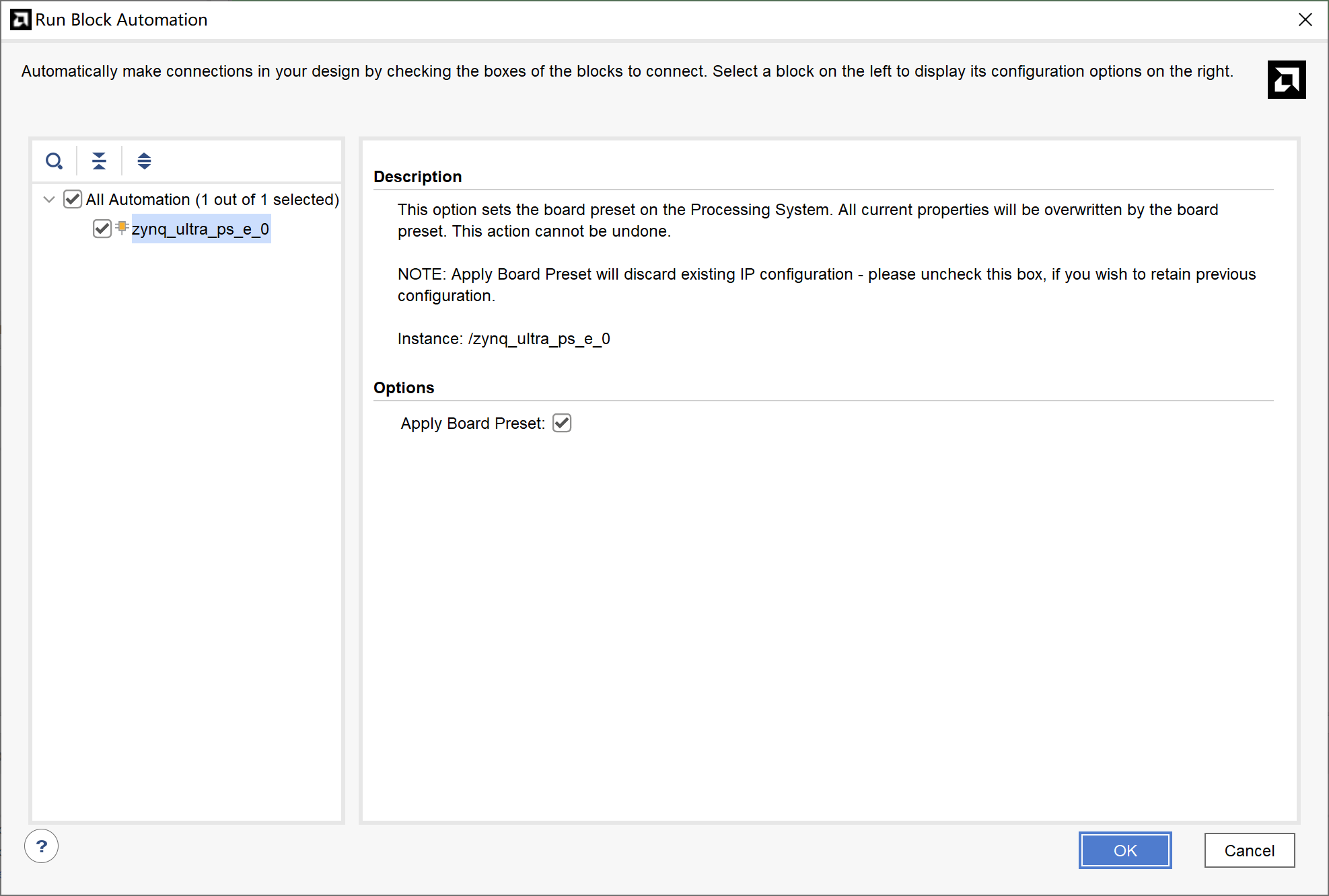
Check the "Apply Board Preset" checkbox and click OK.
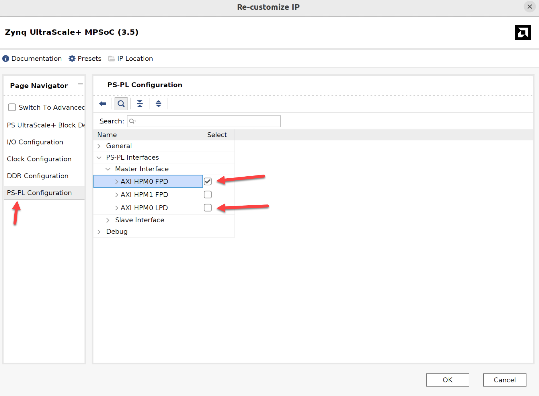
Double-click the "Zynq UltraScale+ MPSoC" module, click "PS-PL Configuration", check "AXI HPM0 FPD" and uncheck "AXI HPM0 LPD" in "PS-PL Interface" > "Master Interface" to complete the configuration of the "Zynq UltraScale+ MPSoC" instance.
¶ Add and Configure PL-side DDR4 Instance
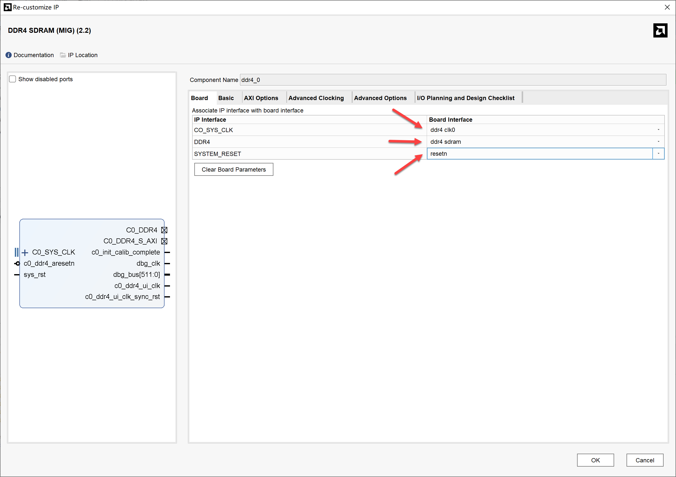
The previous section has successfully configured the PS-side DDR4 and MIO configuration. In addition to a 4GB DDR4 memory on the PS side, this board also has a 2GB DDR4 memory on the PL side. For specific configuration, please refer to the Product Guide. Here we can quickly configure by adding a "DDR4 SDRAM (MIG)" instance and double-clicking it to edit. After selecting as shown in the figure below, click "OK".
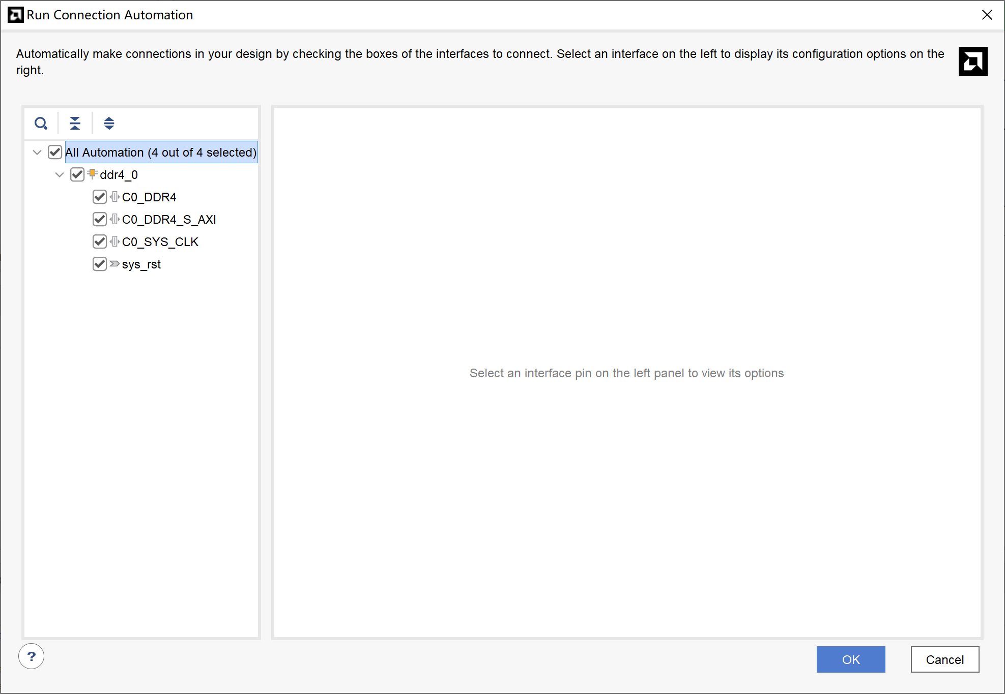
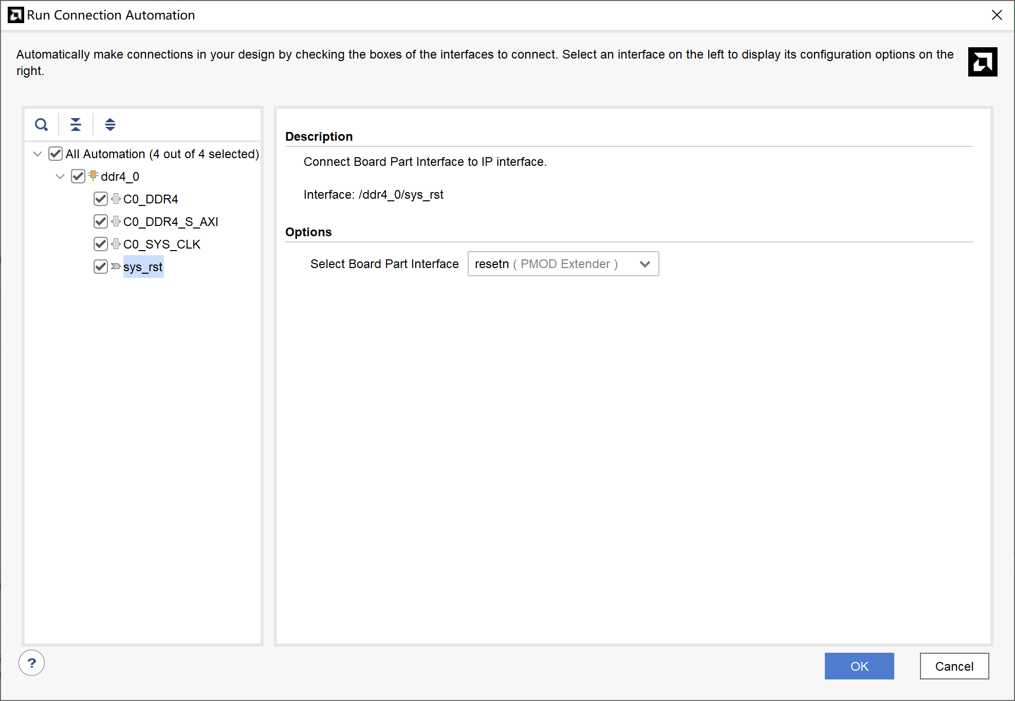
After configuration is complete, click the automatically popped up "Run Connection Automation" and check "All Automation", while switching the "sys_rst" option to "resetn", then click "OK".
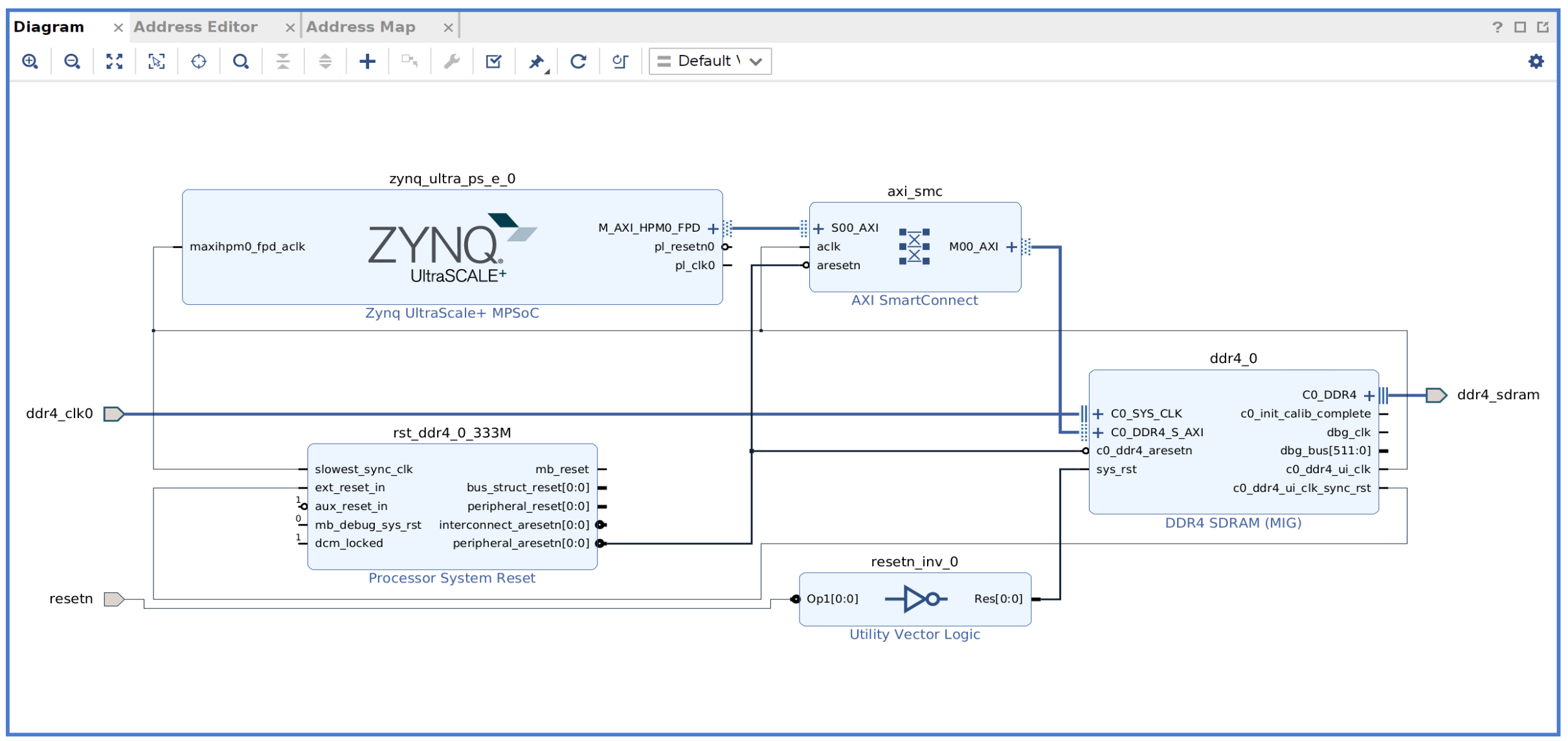
If the operation is correct, the final result should be as follows.
If all settings are correct, you can directly click "Generate Bitstream" to generate the "BIT" file.
¶ Create Vitis Project
After successfully generating the "BIT" file in the previous section, click "File" > "Export" > "Export Hardware..." in Vivado, then select "Include bitstream" in the "Output" tab to export the ".xsa" file.
¶ Create a Platform Project
First, use the ".xsa" file just generated to create a Vitis platform project.
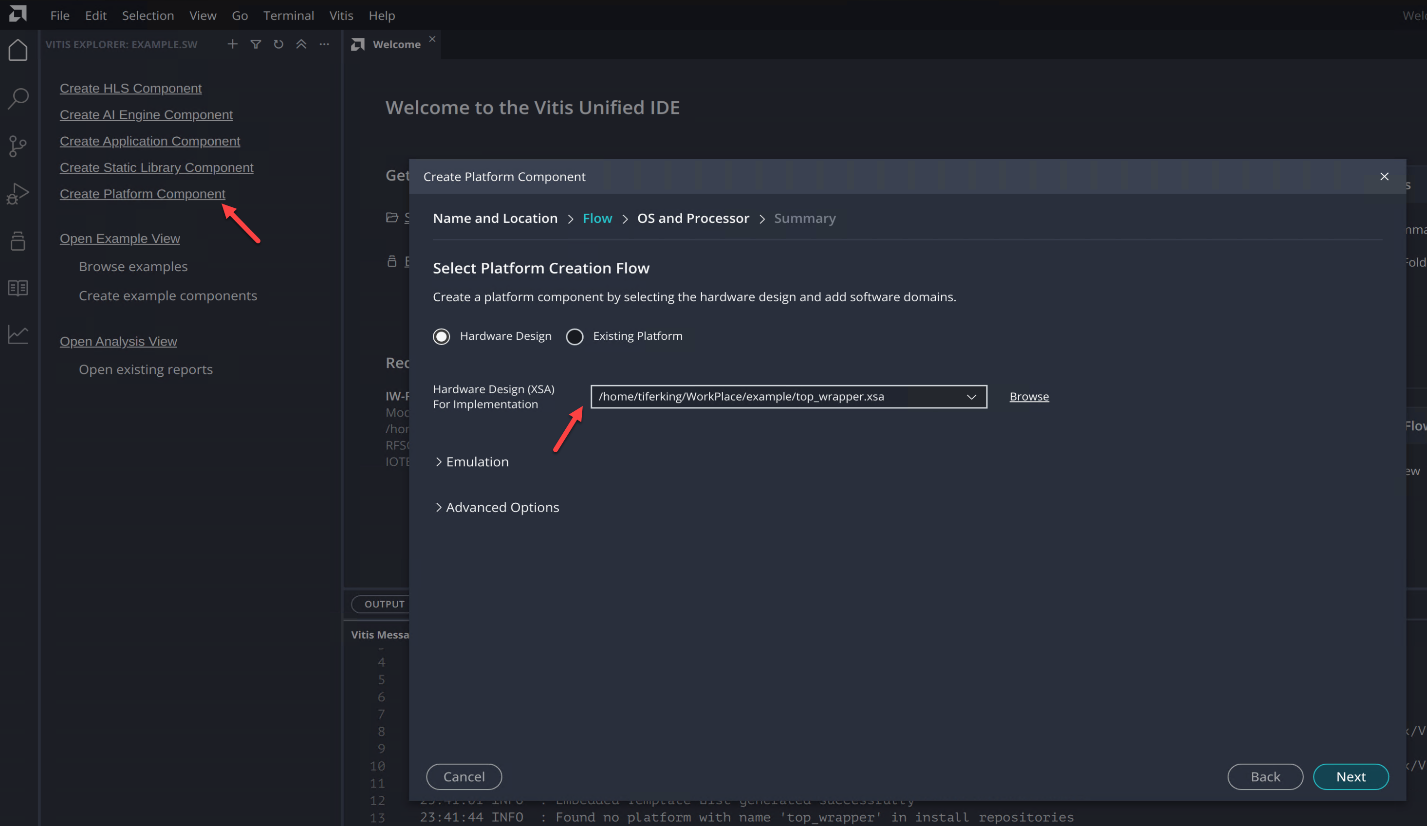
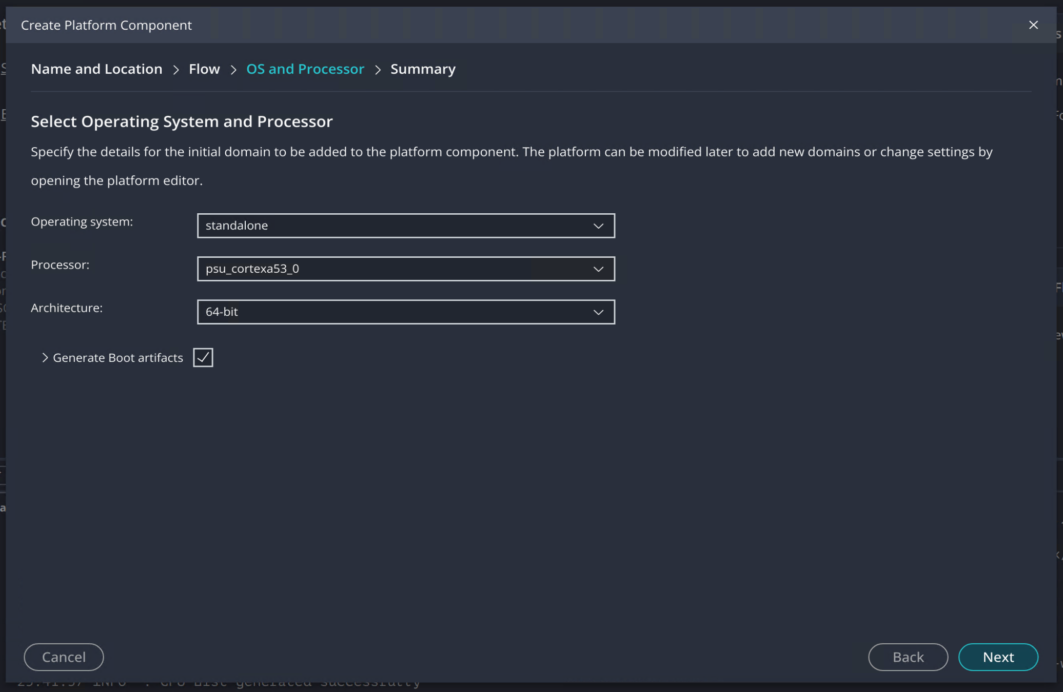
First, select any folder as the Workspace, then click "Create Platform Component" on the left. In the "Flow" stage of the popped-up tab, select the XSA file just generated in "Hardware Design (XSA) For Implementation", as shown in the figure below.
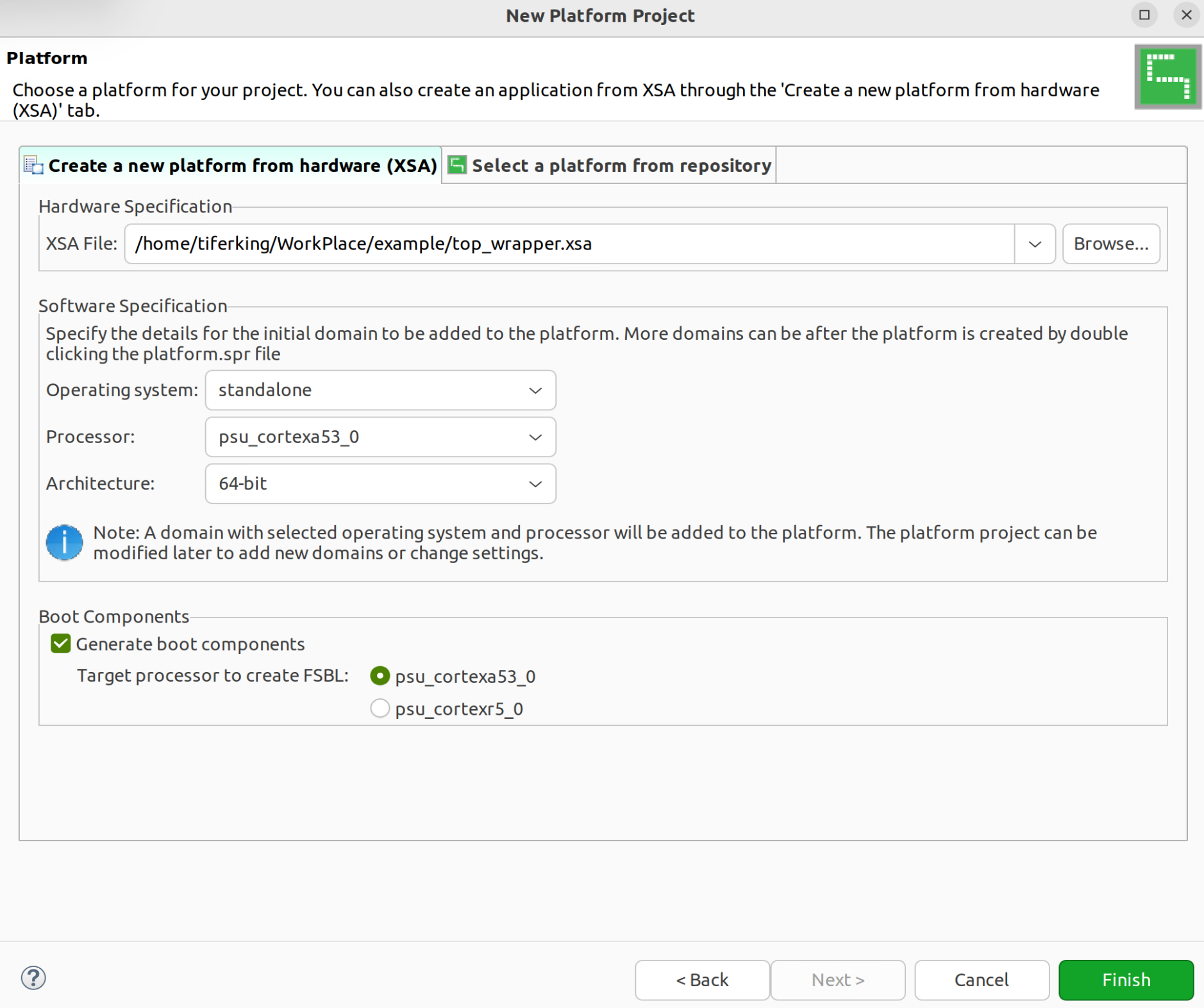
Select "File" > "New" > "Platform Project..." and give it any name (e.g., "plat"). Then select the XSA file just generated in the "Platform" page, as shown in the figure below.
¶ Create Memory Test Project Using Sample Template
Based on the platform project, create an application project and use the "Memory Test" template from the examples to create it.
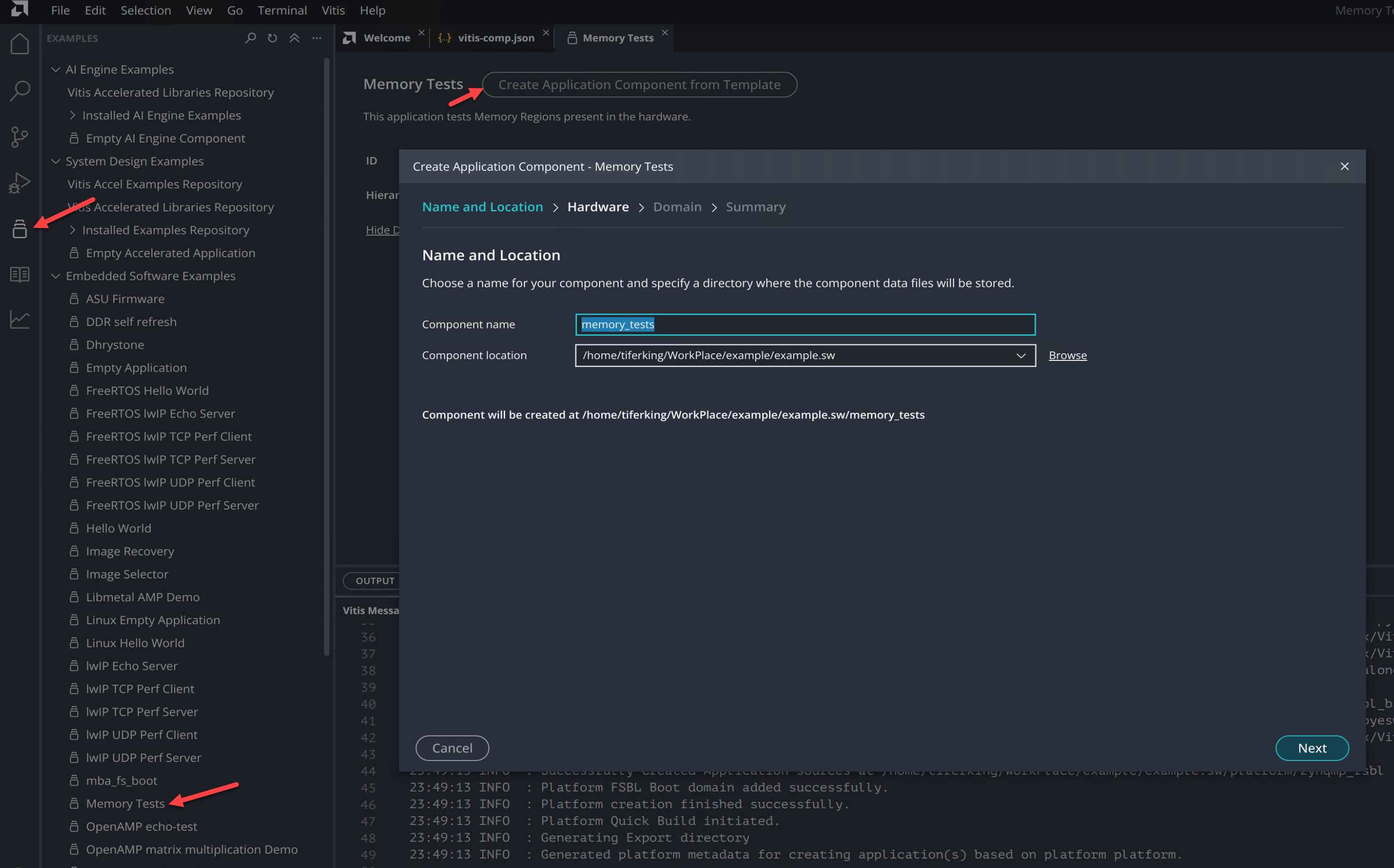
Click the "Examples" tab on the left, select the "Memory Tests" project, and click "Create Application Component from Template" in the tab to create the project from the template.
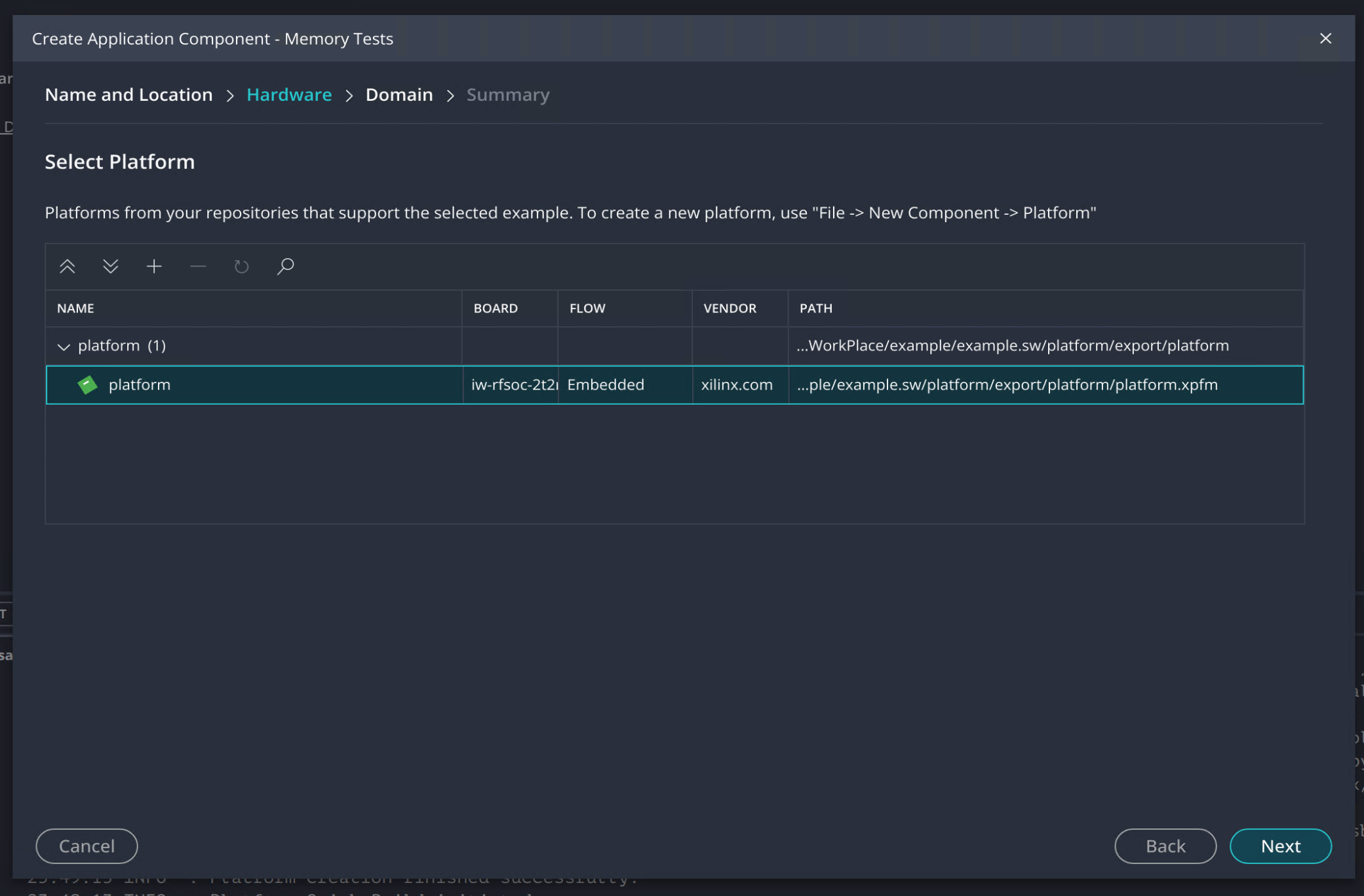
Select the platform project created earlier in the "Hardware" stage.
After compiling and linking the program, open the serial port debugging tool and download the program to the board via JTAG. You can get the following output.
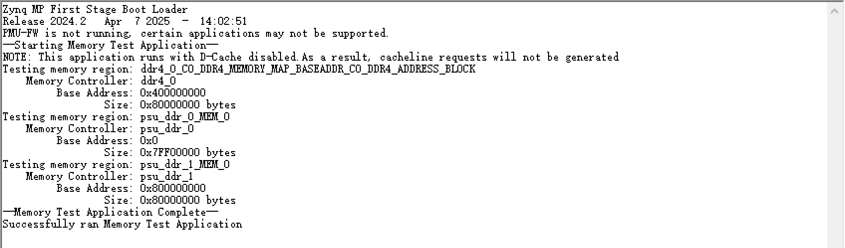
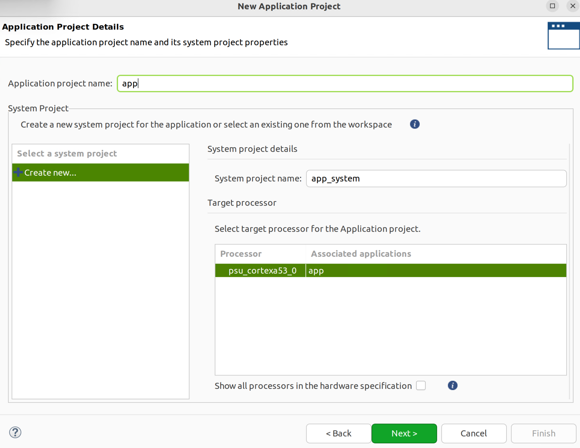
Select "File" > "New" > "Application Project..." and select the platform ("plat") created earlier in the "Platform" tab. Then set it up as follows in the "Application Project Detail" tab.
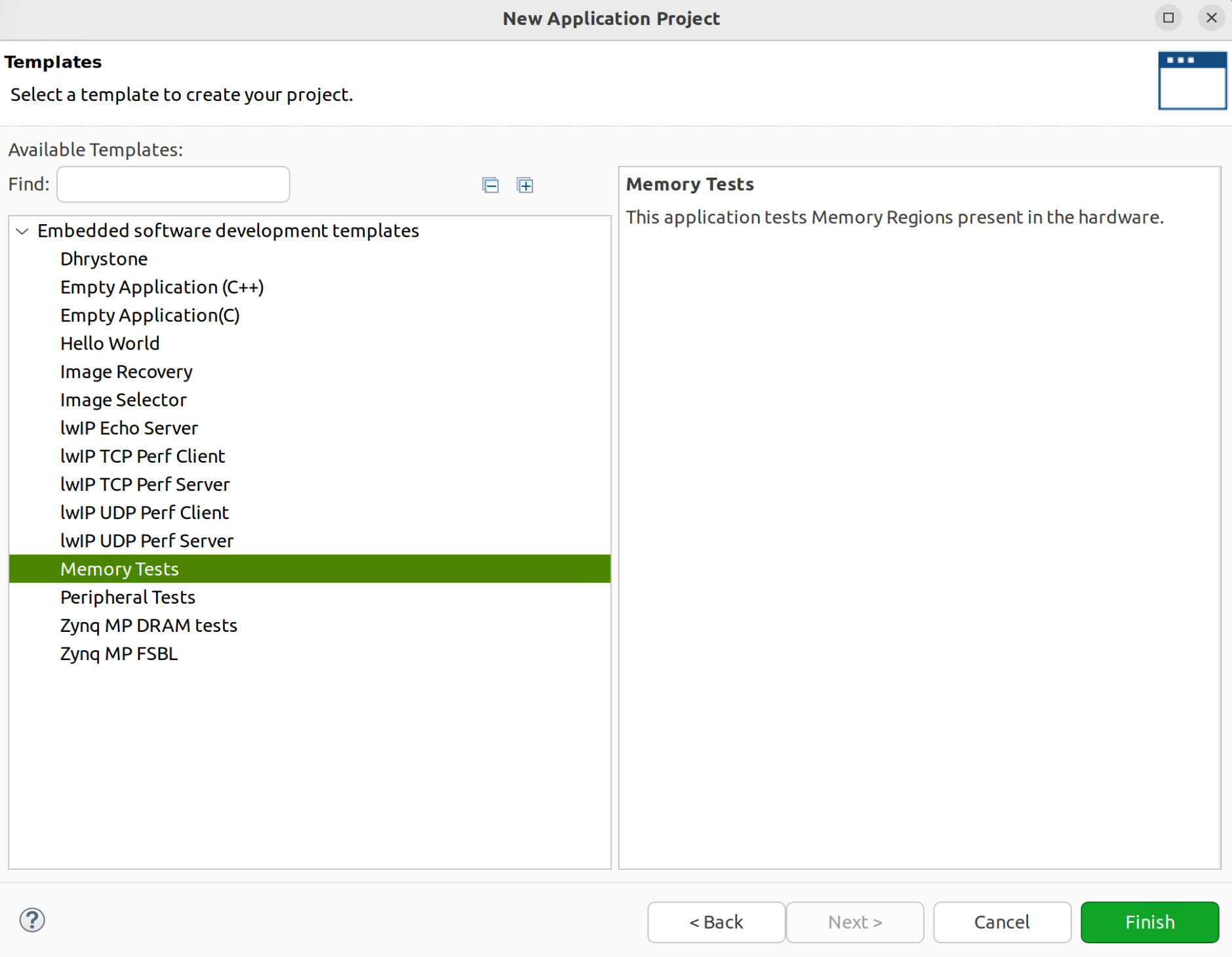
Select the "Memory Tests" project in the "Templates" tab and create it.
After compiling and linking the program, open the serial port debugging tool and download the program to the board via JTAG. You can get the following output.
¶ Create More Detailed Test Project
Based on the platform project, you can also create a more detailed test project for the "Zynq" board, using the "Zynq MP DRAM tests" template to create it.
Click the "Examples" tab on the left, select the "Zynq MP DRAM tests" project, and click "Create Application Component from Template" in the tab to create the project from the template. After compiling and linking the program, open the serial port debugging tool and download the program to the board via JTAG. You can get the following output.
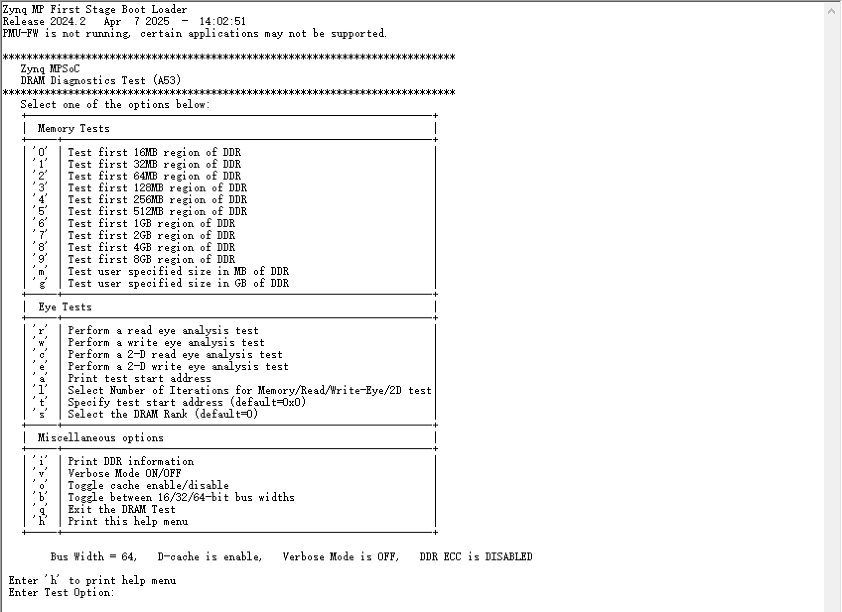
Select the "Zynq MP DRAM tests" project in the "Templates" tab of the previous section and create it. After compiling and linking the program, open the serial port debugging tool and download the program to the board via JTAG. You can get the following output.
According to the menu prompts, you can perform more detailed memory tests.